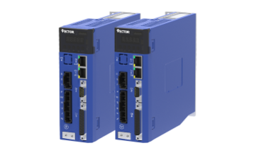
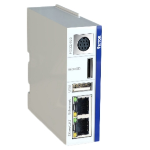
Before telling this problem, first of all, we should be clear about the purpose of the servo motor, relative to the ordinary motor, the servo motor is mainly used for accurate positioning, so we usually say the control servo, in fact, is the position control of the servo motor. In fact, the servo motor also uses two other modes of operation, that is, speed control and torque control, but the application is less. Speed control is generally realized by frequency converter. Speed control with servo motor is generally used for rapid acceleration and deceleration or precise speed control, because relative to the frequency converter, the servo motor can reach thousands of revolutions within a few millimeters.
Because the servo is closed-loop, the speed is very stable. Torque control is mainly to control the output torque of the servo motor, also because of the fast response of the servo motor. Application of the above two kinds of control, you can take the servo drive as a frequency converter, generally with analog control.
The main application of servo motor or positioning control, so this paper focuses on PLC position control of servo motor. Position control has two physical quantities that need to be controlled, that is, speed and position. Specifically, it is to control how fast the servo motor reaches where it is and to accurately stop.
The servo driver controls the distance and speed of the servo motor by the frequency and number of pulses it receives. For example, we agreed that the servo motor would turn every 10,000 pulses. If the PLC sends 10,000 pulses in a minute, then the servo motor completes a circle at 1r/min, and if it sends 10,000 pulses in a second, then the servo motor completes a circle at 60r/min.
Therefore, PLC is through the control of the pulse to control the servo motor, the physical way to send the pulse, that is, the use of PLC transistor output is the most commonly used way, is generally low-end PLC using this way. And the middle and high end PLC is to communicate the number and frequency of pulses to the servo driver, such as Profibus-DP CANopen,MECHATROLINK-II,EtherCAT and so on. These two methods are just different implementation channels, the essence is the same, for programming, is the same. Except for the pulse reception, the control of the servo drive is exactly the same as that of the inverter.
For program writing, this difference is very big, Japanese PLC is to use the way of instruction, and European PLC is to use the form of functional blocks. But the essence is the same, such as to control the servo to go an absolute positioning, you need to control the PLC output channel, pulse number, pulse frequency, acceleration and deceleration time, and need to know when the servo driver positioning is complete, whether to meet the limit and so on. No matter what kind of PLC, it is nothing more than the control of these physical quantities and the reading of motion parameters, but different PLC implementation methods are not the same.

The above is the summary of the PLC (programmable controller) control servo motor, then we come to understand the installation of PLC programmable controller precautions.
PLC program controller has been widely used in various fields, because its internal consists of a large number of electronic components, easy to be affected by some surrounding electrical components interference, strong magnetic field electric field, ambient temperature and humidity, vibration amplitude and other factors affect the normal work of PLC controller, this is often ignored by many people. Even if the program is better, according to the installation link does not pay attention to, after debugging, running will bring a lot of failures. I’m running around trying to maintain it.
The following are precautions for installation:
1. PLC installation environment
a, the ambient temperature ranges from 0 to 55 degrees. If the temperature is too high or too low, the internal electrical components will not work properly. Take cooling or warming measures if necessary
b, the ambient humidity is 35%~85%, the humidity is too high, the electrical conductivity of electronic components is enhanced, easy to reduce the voltage of components, current is too large and breakdown damage.
c, can not be installed in the vibration frequency of 50Hz, amplitude is more than 0.5mm, because the vibration amplitude is too large, resulting in the internal circuit board of electronic components welding, fall off.
d, inside and outside the electrical box should be as far as possible away from the strong magnetic field and electric field (such as control transformer, large capacity AC contactor, large capacity capacitor, etc.) electrical components, and easy to produce high harmonic (such as frequency converter, servo driver, inverter, thyristor, etc.) control devices.
e, avoid loading in places with metal dust, corrosion, combustible gas, moisture, etc
f, it is best to put the electrical components in the upper part of the electrical box, away from the heat source, and consider cooling and outward air exhaust treatment when necessary.
2. Power supply
a, to correctly access PLC power supply, there are points of direct contact. Such as Mitsubishi PLC DC24V; AC voltage is more flexible input, the range is 100V~240V (allowed range 85~264), the frequency is 50/60Hz, no need to pull the switch. It is best to use isolation transformer to supply PLC power.
b, for PLC output DC24V is generally used for extended function module power supply, external three-wire sensor power supply or other purposes, although the output DC24V power supply has overload and short-circuit protection devices and limited capacity. It is recommended that the external three-wire sensor use an independent switching power supply to prevent short circuit, which may cause PLC damage and lead to unnecessary trouble.

3. Wiring and direction
When wiring, it should be crimped with cold press tablet and then connected to the input and output terminals of PLC. It should be tight and secure.
When the input is DC signal, such as the surrounding interference sources and more, should consider a shielded cable or twisted pair, the online direction should not be parallel to the power line and can not be placed in the same line slot, line tube, to prevent interference.
4. Ground
The grounding resistance should not be greater than 100 Ohms. If there is a ground bar in the electrical box, connect it directly to the ground bar. Do not connect it to the ground bar after connecting it to the ground bar of other controllers (such as frequency converters).
5. Others
a, PLC can not be vertical, horizontal according to the installation, such as PLC is fastening, according to the installation of screws to tighten, not loose, in case of vibration, damage to the internal electronic components, if the card rail, must choose qualified card rail, first pull the lock and then into the card rail, and then push the lock, after the PLC controller can not move up and down.
b, if the relay output type, its output point current capacity is 2A, so in a large load (such as DC clutch, solenoid valve), even if the current is less than 2A, should consider using relay transition.
Post time: May-20-2023


